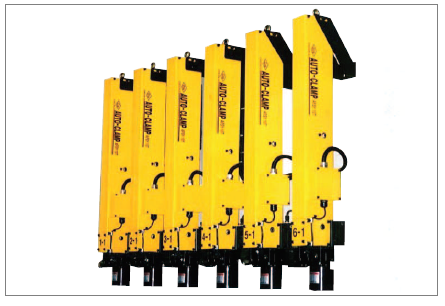
AFSY SERIES
Description

◆Features
•AFSY is slide-transfer type Auto-clamp in which the single-acting spring
restoring type clamp(GY type hi-clamp)and the air cylinder are combined.
•Due to the built-in compact hydraulic hoes and cables, there is no
interference with the feed bar on transfer line or others.
◆Appellation
AFSY ①②③④⑤ -A
| ①
Nominal clamping force (at 250kgf/ ㎠ ) |
|
| 4 | 4ton |
| 6 | 6ton |
| 10 | 10ton |
| ② T-Slof measure | |
| S | 28 |
| M | 32 |
| L | 36 |
| ③ PROXIMITY S/W | |
| D | DC 24V |
| A | AC 90-250V |
| ④ Clamping height : L(mm) |

| ⑤ 이동 STROKE : S(mm) |

| ⑥ Installed leg length : P(mm) |

◆Type & Specifications
| CLAMP Part of clamp | |||
| Type | AFSY 4 | AFSY 6 | AFSY 10 |
| Internal pressure (kgf/㎠) | 375 | ||
| Maximum applicable Pressure (kgf/㎠) | 185 | ||
| Maximum Clamping Force (ton) | 4.0 | 6.0 | 10.2 |
| CLMAP LOAD (ton) | 4.2 | 6.0 | 10.5 |
| Required quantity of Oil (ML) | 13 | 21 | 35 |
| Applicable temperature range (℃) | -5~60℃ (But, unfrozen-conditioned) | ||
| Applicable Oil | (ISOVG32-VG56) General Hydraulic Working Oil | ||
| ACTUATER Actuator to moving | ||
| Type | (kgf/㎠) | 9 |
| Internal pressure (kgf/㎠) | (kgf/㎠) | 4~6 |
| Applicable pressure range | 400, 600, 800(mm) | |
| Propelling power | 20kG(Air Pressure 4kg/ ㎠ ) | |
| Slide-transfer speed | 4-6meter/min. (adjustable by speed control valve). | |
| Applicable Oil | (kgf/㎠) | AIR(No feeding) |
| PROXIMITY SWITCH | ||
| Method of output | D Switch | AC Switch |
| Supplied electric pressure | DC10-30V | AC90-250V(50-60Hz) |
| Applicable temperature | (℃)-25~+75℃ (Unfrozen-conditioned) | |
| Applicable humidity
(OD/RH) |
35~95 | |
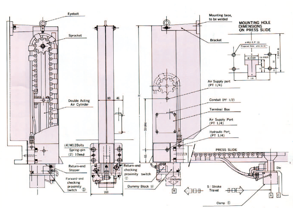
◆Descriptions of Operating Conditions
1) UNCLAMP – Back Moving (Return) Motion
The diagram shows the state of the complete clamping.
In this state, tune the hydraulic valve(SOL C) On, and the oil in the clamp ④
returns to the to the tank by the built-in spring Then the clamp ④ is
released to the direction of unclasping. When it is fully released that a gap
between the die and the clamp is formed (by tie control of the timer in the
electric circuit,however,in some cases, by the two separate operations using
the push button on the control panel instead of the timer),turn on the
electronic valve (SOL B). Then the air cylinder moves to the backing
direction (upward),the clamp ④move to the backing position B, and the limit
switch or the proximity switch ⑦starts to work
Caution : When operating the press without using the clamp, tune on the
hydraulic switching valve (SOL C) at the backing position and
clamp(however, this is not applied for the model in which clamping is
automatically done at the backing position)
2) CLAMP – Forward Moving Motion
when the dummy plate⑧is clamped at the backing position, first turn on the
hydraulic switching valve(SOL C) so that the clamp ④is unclasped to bake
2mm(by the control of the timer in the electric circuit, however, in some
cases, by the two separate operations using the push button on the control
panel instead of the timer).
Then turn on the electronic valve(SOL A) that the air cylinder I move to the
proceeding direction (downward), the clamp④ move to the die position A,
and the limit switch for detecting die or the proximity switch ⑤ start to work.
Then turn off the hydraulic switching valve(SOL C) so that the die is
clamped. However, when there is no die, the clamp proceeds to C and the
limit switch or the proximity switch ⑤ does not work
◆Shape & Measure
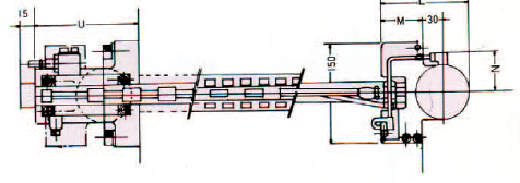
| MODEL NO. | AFSY 6 | AFSY 10 |
| U | 155 | 180 |
| L | 124 | 139 |
| M | 55 | 60 |
| N | 65 | 75 |
◆Circuit diagram
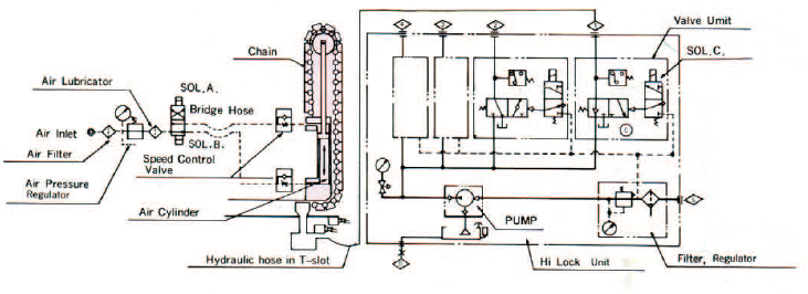
| See also different: | |