DL50
Description

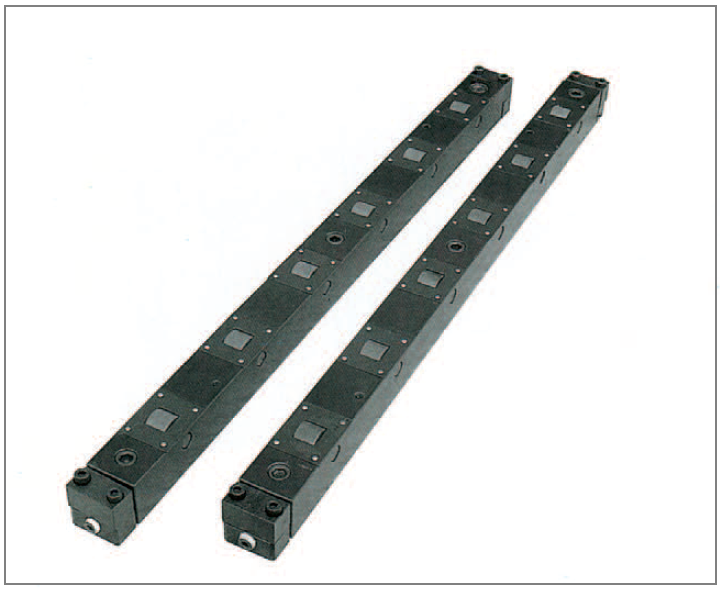
◆Structure & Feature
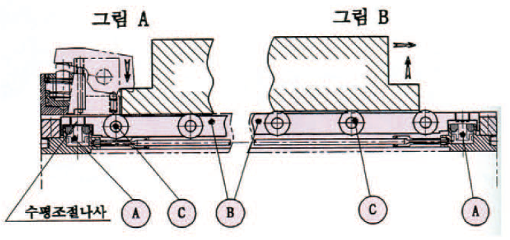
•While moving upward, the hydraulic Cylinder A works by the hydraulic
pressure(While descending, it restores by spring)
•The roller C attached to the Roller bar ascends approximately 2mm above the
bolster surface, and the die is raised as shown in Diagram B
◆CYLINDER

◆Features
(1) A die can be transferred on the roller with the 1/100 or below force of the die
weight.
(2) The cylinders are connected with each other by the O.S.T. high-pressure pipe.
(3) A cover is attached to the roller part for preventing scraps. So this type can be
used safely even where a lot of scraps occur.
(4) The level of the lifter can be adjusted by using the leveling screw.
(5) The protective bushing with the special surface treatment is on the roller in
order to protect the bearing.
| CYLINDER BLOCK | |
| Internal pressure | 375kgf/㎠ |
| Max. working pressure | 185kgf/㎠ |
| Applicable temperature range | 5~60℃ |
DL50 – ① – A
| ① Overall length Die Liffer : L(mm) |
| 300~3400 |
| Measure is according to the output lines |
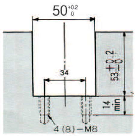
◆Measure of BOLSTER U-slot
◆Shape & Measure

◆Specification & Measure(Normal for L=300~3400)
| ①Overall length of Die Liffer(L) | No. of Cylinders(NC) | No. of Rollers(NR) | No. of Rollers between Cylinders | The allowance weight of minmal number of rollers(kg) | space of cylinders(PC) | space of allcylinders (LC) | space of roller(PR) | space of
all roller(PR) |
||||||||||||||
| No. of Rollers(NRP) | ||||||||||||||||||||||
| 2 | 3 | 4 | 5 | 6 | 7 | 8 | 9 | 10 | 11 | 12 | 13 | 14 | 15 | 16 | ||||||||
| 300 | 2 | 2 | 2 | 202 | 202 | 100 | 100 | |||||||||||||||
| 400 | 2 | 3 | 3 | 750 | 1150 | ※ 1 Nrp is calculated by the following formula. | 302 | 302 | 100 | 200 | ||||||||||||
| 500 | 2 | 4 | 4 | 1500 | LD | 402 | 402 | 100 | 300 | |||||||||||||
| 600 | 2 | 5 | 5 | 500 | 600 | 850 | 1550 | NRP= PR -1LD(mm): Length of mold (direction of loading / unloading) | 502 | 502 | 100 | 400 | ||||||||||
| 700 | 3 | 6 | 3 |
750 |
1150 |
1500 |
1900 |
2250 |
301 | 602 | 100 | 500 | ||||||||||
| 800 | 3 | 6 | 3 | 351 | 702 | 120 | 600 | |||||||||||||||
| 900 | 3 | 8 | 4 |
2650 |
3000 |
401 | 802 | 100 | 700 | |||||||||||||
| 1000 | 3 | 8 | 4 | 451 | 902 | 114 | 800 | |||||||||||||||
| 1100 | 4 | 9 | 3 |
3400 |
334 | 1002 | 112.5 | 900 | ||||||||||||||
| 1200 | 4 | 9 | 3 | 367 | 1102 | 125 | 1000 | |||||||||||||||
| 1300 | 4 | 12 | 4 |
3750 |
4150 |
4500 |
401 | 1202 | 100 | 1100 | ||||||||||||
| 1400 | 4 | 12 | 4 | 434 | 1302 | 109 | 1200 | |||||||||||||||
| 1500 | 4 | 12 | 4 | 467 | 1402 | 118 | 1300 | |||||||||||||||
| 1600 | 5 | 12 | 3 | 375.5 | 1502 | 127 | 1400 | |||||||||||||||
| 1700 | 5 | 16 | 4 | 4900 | 5250 | 5650 | 6000 | 400.5 | 1602 | 100 | 1500 | |||||||||||

◆Selection
•Check the weight of the die that is applied with the minimum number of the rollers(within in the weight limit)
◆Precaution in use
•Leveling (see the diagram of the structure)
•While raising the rollers,adjust that the rollers are approximately2mm above the upper surface of the bolster.
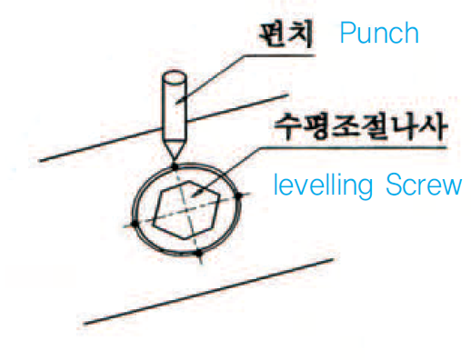
•After completing the adjustment, fix by using the punch(see the diagram on the left for how to fix)
•When the Guide roller is also used, adjust the level so that the height of the roller is the same as that of the roller guide while the die lifter ascending.
•Regularly remove dust or foreign substances in the lifter groove between the lifter bars.
| See also different: | |