
HI-LOCK UNIT
Description
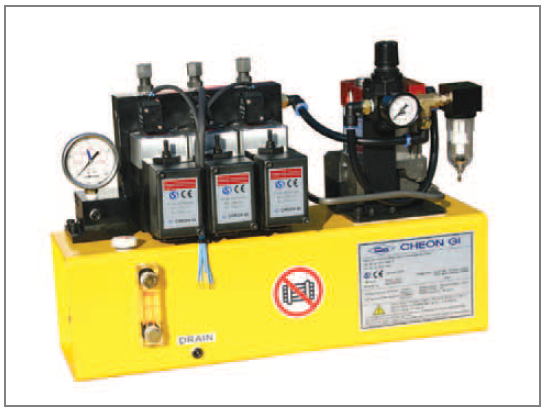
◆Overview
•HU type(hi-lock unit)is a hydraulic device composed of the pump(air drive hydraulic pump) and the air-pilot operating
Direction-valve(non-leak type).
•Since can be attached to the manifold, this unit can be used for different purposes due to various applcations even though it
is a compact type.
•For operating type, the Electrical operating system[HU-S] that can be operated remotely and the Mannual operating system[HU-M]are available.
•The standard type has the pressure gauge and the air filter. With air supply, high hydraulic pressure can be easily obtained
in any condition. So this unit can be applied to the automated machines, such as the clamp party, the locking system, etc
◆Appellation
HU – ① – ②S – ③ – ④ – A
| ① No. of circuits | |
| Non | 1circuit |
| 2 | 2circuit |
| 3 | 3circuit |
| 4 | 4circuit |
| ② No. of acting valve | |
| 1 | 1EA |
| 2 | 2EA |
| 3 | 3EA |
| 4 | 4EA |
| ③ Option | |
| Non | |
| R | Relief valve |
| L | Inter Lock circuit |
| T | One Two circuit |
| ④ PUMP type | |
| 70-8 | 70-8 |
| 70-10 | 70-10 |
| 70-12 | 70-12 |
| 100-12 | 100-12 |
| 100-15 | 100-15 |
◆BOX TYPE
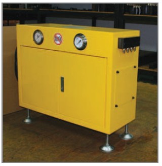
| Standard | SIZE |
| 1S | 506×260×500(H) |
| 2S | 506×260×500(H) |
| 3S | 628×260×500(H) |
| 4S | 680×260×500(H) |
◆Common items
| Maximum applicable pressure | 400kgf/㎠ |
| Maximum air supply pressure | 9.5kgf/㎠ |
| Reducing valve pressure setting range | 2~6kgf/㎠ |
| Applicable temperature range | 35~60℃ |
| Solenoid valve | AC100V/100V AC200V/220V 50/60Hz |
| Applicable oil | General hydraulic oil |
※ These specification can be changed for improvement or other reason without notice.
◆Shapes & Measure
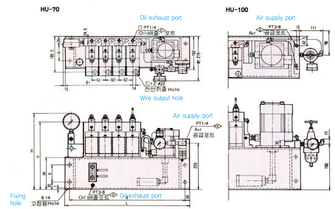
| Type
Specifications |
L | ℓ | ℓ1 | H | h | W | b | t | TANK
CAP、(ℓ) |
Quantity of oil(ℓ) | Weight(kg) |
| HU-1-70- | 393 | 353 | 123 |
380 |
315 |
150 |
80 |
4.5 |
5.7 | 1.4 | 25.5 |
| HU-2-70- | 455 | 415 | 185 | 7.0 | 1.7 | 34.2 | |||||
| HU-3-70- | 517 | 477 | 247 | 8.2 | 2.0 | 42.9 | |||||
| HU-4-70- | 579 | 539 | 123 | 9.4 | 2.3 | 51.6 | |||||
| HU-1-100- | 423 | 383 | 309 |
405 |
340 |
175 |
105 |
6 |
8.6 | 2.7 | 39.0 |
| HU-2-100- | 485 | 445 | 185 | 10.2 | 3.2 | 48.4 | |||||
| HU-3-100- | 547 | 507 | 247 | 11.9 | 3.7 | 57.8 | |||||
| HU-4-100- | 609 | 569 | 309 | 13.5 | 4.3 | 67.2 |
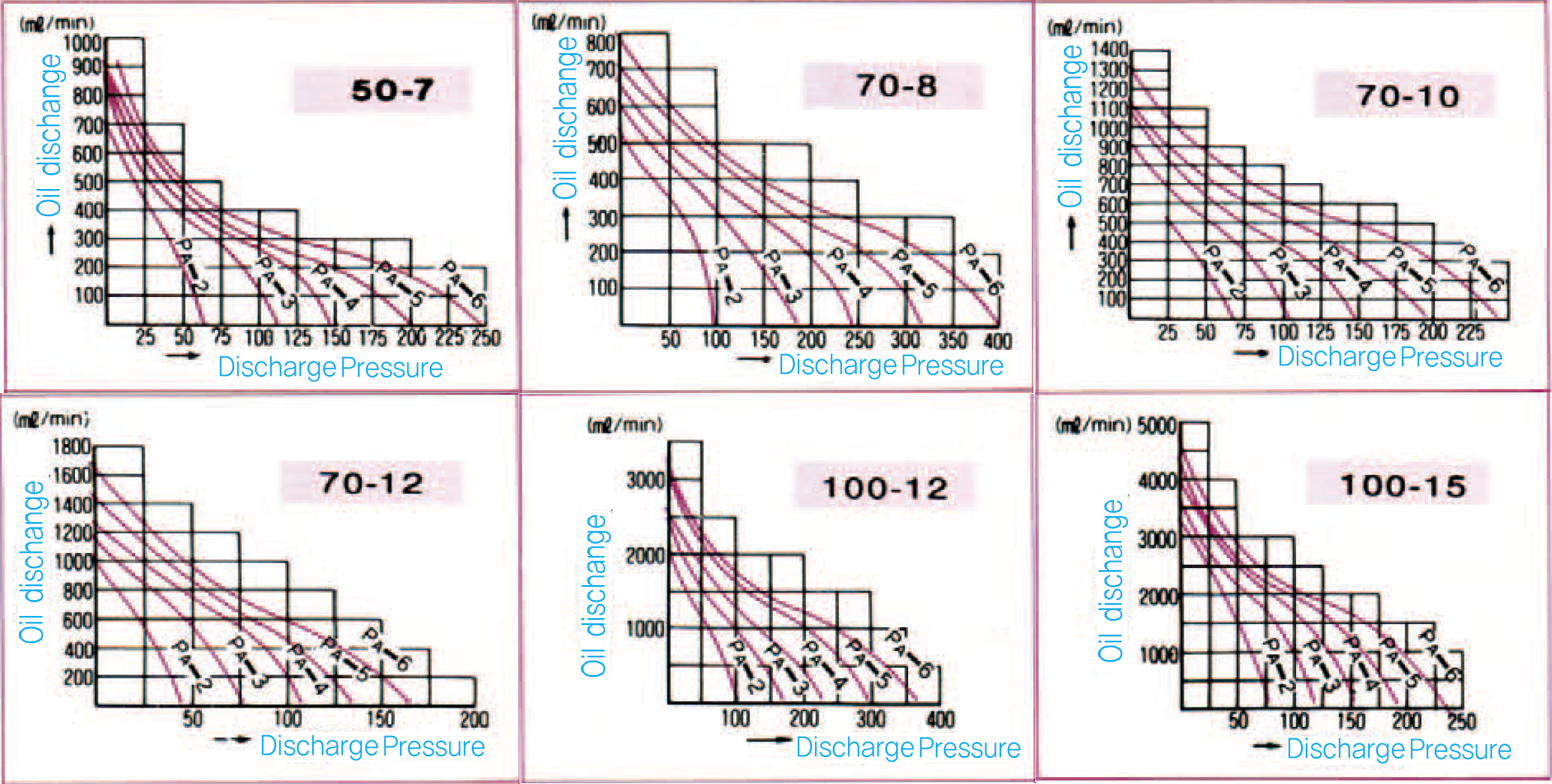
PUMP Flow rate Characteristics.
Conditions : Oil temperature 20℃
PA : supplied air pressure
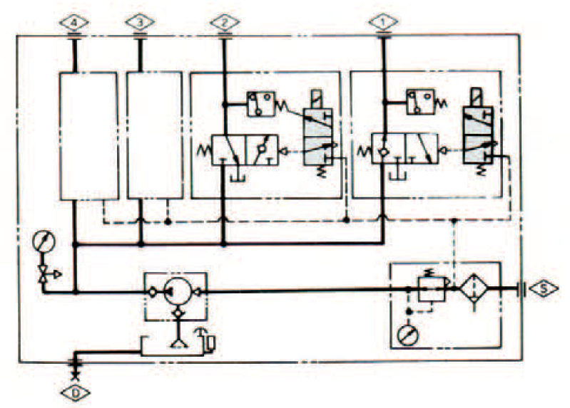
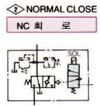
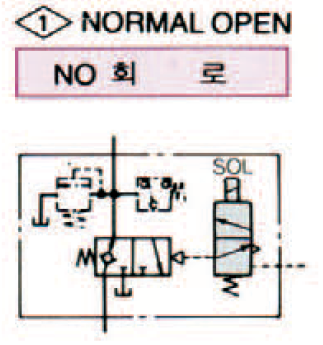
◆Circuit Diagram & Valve Type
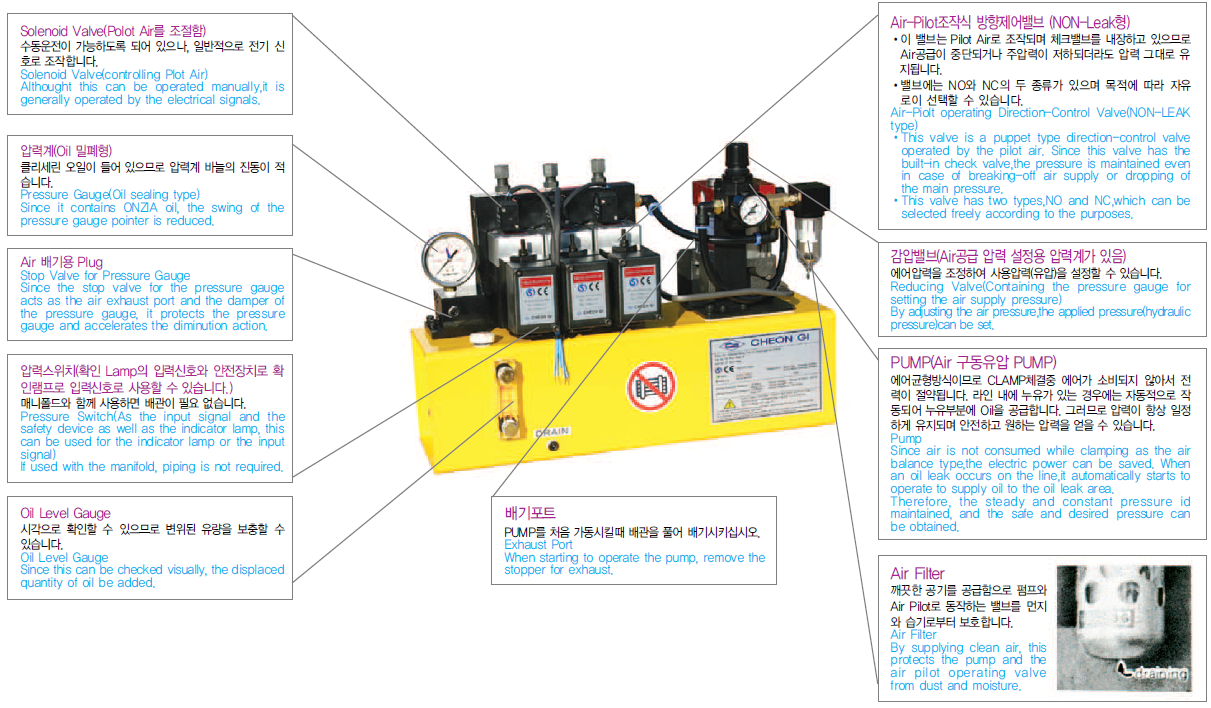
When the solenoid is
turned on,the pressure is
transmitted. This is the
most suitable for the die
lifter
When the solenoid is turned off,
the pressure is transmitted. So
this is the most suitable for the
clamp circuit.(The pressure is
maintained in case of power
failure or breaking-off air supply).
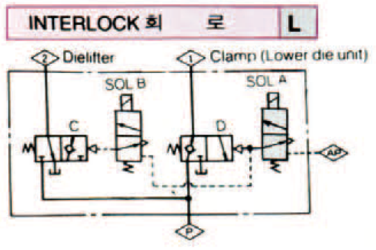
When SOL(A)is turned off, the air-pilot operating direction control valve C
does not operate regardless of SOL(B)-on or OFF. This is the most suitable
for being used between the die lifter and the clamp.
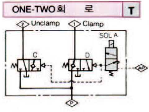
By SOL(A),C and D are operated.
Pressure increase & pressure gauge range
of the pump
| Type | Pressure increase (time) | Pressure gauge range |
| 50-7 | 40 | 350 |
| 70-8 | 65 | 500 |
| 70-10 | 40 | 350 |
| 70-12 | 28 | 250 |
| 100-12 | 62.5 | 500 |
| 100-15 | 40 | 350 |